Pro-Link


Pro-Link bezeichnet ein Hinterrad-Federungssystem für Motorräder der japanischen Firma Honda.
Entgegen dem klassischen Prinzip der Anordnung von zwei Federbeinen an beiden Holmen der Schwinge, die sich am Heckrahmen abstützen, wird beim Pro-Link System nur ein zentrales Federbein, welches in der Fahrzeugmittelachse vor dem Hinterrad in der Nähe des Schwingendrehpunktes stehend angeordnet ist, verwendet. Das Federbein stützt sich oben an einer Quertraverse des Rahmens ab. Die Einfederungskraft wird von einem Kniehebel-Mechanismus und einem oder zwei am Rahmenunterteil gelagerten Verbindungshebel nichtlinear von der Schwinge auf das untere Auge des Federbeins übertragen. Da mit zunehmender Einfederung durch die Gestaltung der Kinematik der übertragene Weg zunimmt, wird eine progressive Feder- und Dämpferkennlinie erzeugt.
Vorteile des Systems sind die progressive Charakteristik und eine tiefe Einbaulage des Federbeins. Der Hebelmechanismus wird von Honda als progressive linkage (= progressive Verbindung) bezeichnet, was sich in dem Akronym Pro-Link widerspiegelt.
Die erste Verwendung fand das System ab 1979 in den Enduro-Modellen des Herstellers. Später folgten auch Straßenmotorräder wie die Honda CBX. Die Weiterentwicklung wird von Honda ab den 2000er als Unit Pro-Link bezeichnet.
- Zeichnungen aus Patent US4360214
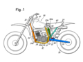
Seitenansicht

Explosionszeichnung

Kennlinie
Weblinks
Auf dieser Seite verwendete Medien

* FIG. 1 is a side view of a motorcycle with a shock absorbing device according to the invention.
- FIG. 2 is a partial side view of the motorcycle in FIG. 1, shown in an enlarged scale, wherein the action of a progressive mechanism during swinging movement of a rear wheel support frame is illustrated.
- FIG. 3 is a partial plan view of the motorcycle in FIG. 2, shown from the bottom.
- FIG. 4 is a perspective view of the shock absorbing device, wherein the components thereof are illustrated in a disassembled state.
- FIGS. 5A, 5B and 5C are side views of exemplary bracket members for use as an engine hanger which is intended to connect a front end of a rod member to a body frame. :
- FIG. 6 is a side view of a shock absorbing device wherein a rotary member in accordance with a modified embodiment of the present invention is employed.
- FIG. 7 is a perspective view of the shock absorbing device in FIG. 6, wherein the device is illustrated in a disassembled state.
- FIG. 8 is a side view of a shock absorbing device in accordance with another modified embodiment of the present invention, wherein an intermediate bracket member is interposed between the rod member and the body frame.
- FIG 9 is a cross sectional view of the shock absorbing device, taken along the line 9-9 in FIG. 8.
- FIG. 10 is a perspective view of the shock absorbing device in FIG. 8, wherein the device is illustrated in a disassembled state.
- FIG. 11 is a partial side view of a shock absorbing device in accordance with another modified embodiment of the present invention, wherein an arrangement is made such that the axial load of the rod member will not impart a twisting force to a bracket secured to the body frame.
- FIG. 12 is a plan view of the body frame and the bracket in FIG. 11, shown from the bottom.
- FIG. 13 is a side view of a shock absorbing device in accordance with another modified embodiment of the present invention, wherein an arrangement is made such that mud carried by the chain is prevented from adhering to the progressive mechanism.
- FIG. 14 is a plan view of the device in FIG. 13.
- FIG. 15 is a side view of a motorcycle for on-road driving provided with a shock absorbing device according to the present invention.
- FIG. 16 is a characteristic diagram showing a shock absorbing property of the shock absorbing device relative to the swinging angle of the rear wheel support frame
- 20 motorcycle
- 21 body frame
- 22 head pipe
- 23 main frame
- 23a bracket
- 24 down tube
- 25 rear frame
- 25a lower part for the rear frame 25
- 25b standing part
- 26 engine
- 28 subframe
- 31 bracket frame
- 32 rear wheel
- 33 support frame
- 33 rear fork
- 34 side plate
- 34a drilled hole
- 34b drilled hole
- 35 side plate
- 35a drilled hole
- 35b drilled hole
- 36 tubular member
- 37 bolt
- 38 bolt
- 41 extions of the side plate 34
- 42 extions of the side plate 35
- 43 tubular projection
- 44 tubular projection
- 50 shock absorber
- 53 rod member
- 53a rod body
- 58 bolt
- 59 bolt
- 61 fuel tank
- 62 seat
Sketch of the Honda Pro-Link suspension
Sketch of the Honda Pro-Link suspension
Autor/Urheber: Rich Niewiroski Jr., Lizenz: CC BY 2.5
2006 Honda CBR600RR Unit Pro-Link swingarm. Camera used was a Nikon Coolpix 5000.

* FIG. 1 is a side view of a motorcycle with a shock absorbing device according to the invention.
- FIG. 2 is a partial side view of the motorcycle in FIG. 1, shown in an enlarged scale, wherein the action of a progressive mechanism during swinging movement of a rear wheel support frame is illustrated.
- FIG. 3 is a partial plan view of the motorcycle in FIG. 2, shown from the bottom.
- FIG. 4 is a perspective view of the shock absorbing device, wherein the components thereof are illustrated in a disassembled state.
- FIGS. 5A, 5B and 5C are side views of exemplary bracket members for use as an engine hanger which is intended to connect a front end of a rod member to a body frame. :
- FIG. 6 is a side view of a shock absorbing device wherein a rotary member in accordance with a modified embodiment of the present invention is employed.
- FIG. 7 is a perspective view of the shock absorbing device in FIG. 6, wherein the device is illustrated in a disassembled state.
- FIG. 8 is a side view of a shock absorbing device in accordance with another modified embodiment of the present invention, wherein an intermediate bracket member is interposed between the rod member and the body frame.
- FIG 9 is a cross sectional view of the shock absorbing device, taken along the line 9-9 in FIG. 8.
- FIG. 10 is a perspective view of the shock absorbing device in FIG. 8, wherein the device is illustrated in a disassembled state.
- FIG. 11 is a partial side view of a shock absorbing device in accordance with another modified embodiment of the present invention, wherein an arrangement is made such that the axial load of the rod member will not impart a twisting force to a bracket secured to the body frame.
- FIG. 12 is a plan view of the body frame and the bracket in FIG. 11, shown from the bottom.
- FIG. 13 is a side view of a shock absorbing device in accordance with another modified embodiment of the present invention, wherein an arrangement is made such that mud carried by the chain is prevented from adhering to the progressive mechanism.
- FIG. 14 is a plan view of the device in FIG. 13.
- FIG. 15 is a side view of a motorcycle for on-road driving provided with a shock absorbing device according to the present invention.
- FIG. 16 is a characteristic diagram showing a shock absorbing property of the shock absorbing device relative to the swinging angle of the rear wheel support frame
- 20 motorcycle
- 21 body frame
- 22 head pipe
- 23 main frame
- 23a bracket
- 24 down tube
- 25 rear frame
- 25a lower part for the rear frame 25
- 25b standing part
- 26 engine
- 28 subframe
- 31 bracket frame
- 32 rear wheel
- 33 support frame
- 33 rear fork
- 34 side plate
- 34a drilled hole
- 34b drilled hole
- 35 side plate
- 35a drilled hole
- 35b drilled hole
- 36 tubular member
- 37 bolt
- 38 bolt
- 41 extions of the side plate 34
- 42 extions of the side plate 35
- 43 tubular projection
- 44 tubular projection
- 50 shock absorber
- 53 rod member
- 53a rod body
- 58 bolt
- 59 bolt
- 61 fuel tank
- 62 seat