Bumpmapping
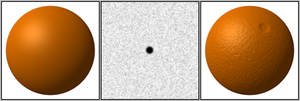
Bumpmapping ist eine Technik, die in 3D-Visualisierungsprogrammen zum Einsatz kommt, um den Detailreichtum von Objekten zu verbessern, ohne dabei deren Geometriekomplexität zu erhöhen. Der Trick dabei ist, dass die benötigten Informationen in einer Textur gelagert werden, mit deren Hilfe Schattierungen auf eine Oberfläche gezeichnet werden.
Bumpmapping ist somit nur eine (wenngleich wirksame) Illusion, welche Oberflächenunebenheiten simuliert, die in der Geometrie des Modells gar nicht vorhanden sind.
Es verbessert die Bildqualität und den Realismusgrad, ohne sich wesentlich auf die für das Rendern benötigte Zeit niederzuschlagen. Außerdem ist das Einsatzgebiet nicht nur auf Schattierungen begrenzt. Reflexionen können mit dieser Technik genauso behandelt werden. Bumpmapping spielt bereits eine große Rolle in Projekten der Unterhaltungsindustrie, da sich die visuelle Qualität deutlich verbessern lässt, ohne die Leistung dabei nennenswert zu beeinträchtigen.
Voraussetzung für die Verwendung von Bumpmaps ist ein Beleuchtungsmodell, das auf Per-Pixel-Lighting basiert. APIs wie DirectX oder OpenGL haben die nötigen Routinen bereits vorliegen. Meistens wird jedoch eine Kombination aus Vertex- und Pixel-Shadern verwendet, um die nötigen Effekte exakt zu kontrollieren.
Das Verfahren wurde 1978 von James F. Blinn entwickelt.
Height-Mapping
Die relativen Höheninformationen liegen in einer Textur in Form von Graustufen vor – der sogenannten Heightmap. Jeder Grauwert steht für eine bestimmte Höhe. Normalerweise ist Schwarz (Wert 0) die „tiefste“ Stelle und Weiß (Wert: 255) die „höchste“. Diese Form der Datenspeicherung ist nicht nur auf Bumpmapping beschränkt, viel öfter kommt sie bei der Generierung von riesigen Terrains zum Einsatz.
Da Höhenunterschiede nur durch verschiedene Graustufen auf der Textur vorgegaukelt werden, die Flächen aber glatt bleiben, treten einige sichtbare Fehler auf:
- Bei flachem Betrachtungswinkel wirkt die Struktur stark verzerrt.
- Die Silhouette bleibt so eben wie beim ursprünglichen Objekt.
- Es wird ein glatter Schatten geworfen.
- Bumps werfen keine Schatten aufeinander.
Anwendung
- Texture Baking
Der 3D-Modeller baut zwei Versionen eines Modells auf: eine hochauflösende, sehr detailreiche (100.000+ Polygone) und eine für das fertige Programm bestimmte, undetaillierte (100–10.000 Polygone). Ein Programm berechnet den Unterschied zwischen den beiden Modellen und beschreibt mit den gewonnenen Daten eine Textur. Diese Textur wird dann auf das Low-Poly-Modell gespannt. Im fertigen Spiel/Bild/Anwendung bekommt der Benutzer den Eindruck, dass das hochdetaillierte Modell verwendet wird.
- Erstellen von Hand
Bei einfachen Formen (Ritzen, hervorgehobenem Text) und Details, die ebenfalls in einer von Hand erstellten Farbtextur auftauchen (abgeblätterter Lack, Macken, Nieten) wird oft eine Bumpmap von Hand erstellt, indem mit hellen und dunklen Formen und Linien die gewünschten Bereiche herausgehoben oder vertieft werden, beziehungsweise die Farbtextur so bearbeitet und in Graustufen umgewandelt wird, dass der gewünschte Effekt erzielt wird.
Siehe auch
Weblinks
- Bump Mapping (englisch, Webarchiv)
Auf dieser Seite verwendete Medien
Mapowanie wypukłości (przykład, POV-Ray)
Autor/Urheber:
- Bump-map-demo-smooth.png, Orange-bumpmap.png and Bump-map-demo-bumpy.png: Original uploader was Brion VIBBER at en.wikipedia
Later version(s) were uploaded by McLoaf at en.wikipedia.
- derivative work: GDallimore (talk)
Combined w:bump mapping demo from: File:Bump-map-demo-smooth.png, File:Orange-bumpmap.png and File:Bump-map-demo-bumpy.png
A raytraced image created with w:POV-Ray illustrating the limitations of w:bump mapping.
On the left is a perfect sphere which has been given a wrinkled surface using a bump map. Mathematically, POV-Ray's internal "agate" function is used to define a value for each point on the surface of the sphere. This value is used as an apparent height of the sphere's surface above or below where the surface should be and this changes the way that light is simulated to reflect from the surface of the sphere. However, its size and shape are not changed in 3D-space. Consequently, the object's outline and the shadow cast on the ground remain those of a perfect, non-bumpy sphere. An unrealistic hard shadow is also visible on the surface of the sphere, about a third of the way from the top.
On the right is a roughly spherical object on which wrinkles have been modelled in 3D-space. Mathematically, the same "agate" function is subtracted from a function defining a sphere, x2+y2+z2-Radius2, and all points in space where this sum is zero define the surface of the resulting object, referred to as an w:isosurface. This results in an object that is a modification in 3D-space of an otherwise perfect sphere. Consequently, the object's outline and the shadow cast on the ground are also visibly wrinkled, and the shadowing on the surface of the object is more realistic.
Possible wikipedia image text:
In 3D computer graphics, bumps, wrinkles and dents can be simulated by using bump mapping. A bump map changes the way an object's surface appears to reflect or refract light and can increase the realism of computer-generated images without significantly increasing render times. The technique is limited in that it does not modify the shape of the underlying object in 3D-space. On the left, a mathematical function defining a bump map simulates a crumbling surface on a perfect sphere, but the sphere's outline and shadow are unaffected. On the right, the same function is used to model a roughly spherical object by generating an isosurface. The object's outline and shadow are therefore more realistic.
POV-Ray code:
#version 3.6;

global_settings {
  assumed_gamma 1.0
  ambient_light 0
  radiosity {
    pretrace_start 0.08
    pretrace_end   0.04
    count 35
    nearest_count 5
    error_bound 1.8
    recursion_limit 3
    low_error_factor .5
    gray_threshold 0.0
    minimum_reuse 0.015
    brightness 1

    adc_bailout 0.01/2
    normal on
    media off
    always_sample on
    max_sample 1.0
   }
 }

fog{
  fog_type 1
  distance 9
  rgb 0
  turbulence 5
 }

// ----------------------------------------

camera {
  location  <0.0, 1.5, -4>
  direction z
  right     x*image_width/image_height
  look_at   <0.0, 0,  -1.4>
}

light_source { <0, 5, -3>  color rgb <1, 1, 1>*.6
  area_light  <3,0,0>,<0,0,3> 10,10 orient  circular
  }

light_source { <0, 100, 80>  color rgb <1, 1, 1> }

// ----------------------------------------

plane {
  y, -1
  pigment { color rgb 1 }
  finish {ambient 0}
}

#declare mytex=texture{pigment { colour rgb <1,0,0>  }
     finish{ specular 0.09 roughness .0075 diffuse .85 ambient 0 reflection 0.0}}

#include "functions.inc"

#declare bump_func=function{f_agate(x/.5,y/.5,z/.5)*.1}
#declare sphere_func=function(x,y,z,Radius,xoff,yoff,zoff){pow(x-xoff,2)+pow(y-yoff,2)+pow(z-zoff,2)-pow(Radius,2)}

isosurface {
    function {sphere_func(x,y,z,1,0,0,0)-bump_func(x,y,z)*.71}
    max_gradient 8
    contained_by { sphere { 0, 1.5 } }
    texture {mytex}
    translate x*1.5
    }

sphere {  0, 1
  texture {mytex
    normal {function {bump_func(x,y,z)*10*.25} accuracy .0002 bump_size 1}
    }
    rotate -y*32
    translate -x*1.5
  }


